Pv Diagram Gas Turbine Engine
Turbojet vs. turbofan: safety, efficiency, and performance – airplane Brayton cycle Mechanical engineering
Gas turbine power plant- construction and working
(a): idealized brayton cycle for gas turbines, (b): t-s diagram, (c Turbine constant Use of natural gas production for a thermoelectric power generation plant
Brayton reheat intercooling cycles thermodynamics thermodynamic
Brayton turbine ericsson reverse closed nuclear cycles thermodynamics thermodynamic turbinesConstant pressure open and closed cycle gas turbine # s. v. nishandar Turbine diagram gas cycle closed working pv various mechanical booster construction processes usedTurbine cogeneration desalting.
Diesel cycle: process, pv diagram, efficiency with derivationGas turbine power plant- construction and working Gas turbine schematic and station numbersBrayton thermodynamic turbojet turbofan piston thrust pv pressure thermodynamics augmentation.

Schematic diagram of gas turbine
Closed cycle gas turbine: construction, working, diagramPv engine combustion dieselmotor mesin diagramm ciclo process derivation explanation schema diagramma interna siklus motore Brayton cycleBrayton turbines idealized.
Pv cyclesTurbine gas diagram boiler working principle steam figure All about general electric pg 9171 e gas turbineSteam boiler: working principle of gas turbine.

Turbine gas efficiency aircraft engine increasing ratios compression designers manufacturers focus general engineering
Turbine gas schematic nasa engine station aircraft numbers number engines parts airplane jet gif modern location each military drawings glennJet engine pv diagram Pv heat diagrams enginesTurbine gas engine diagram power combustion plant natural internal generation specific energy turbines aircraft education use thermoelectric production figure courtesy.
Gas turbine diagram flow simple turbines electric cycle axial general starting support pg unit tutorialsPv diagrams and heat engines Turbine gas pv cycle.


Constant Pressure Open and Closed Cycle Gas turbine # S. V. Nishandar

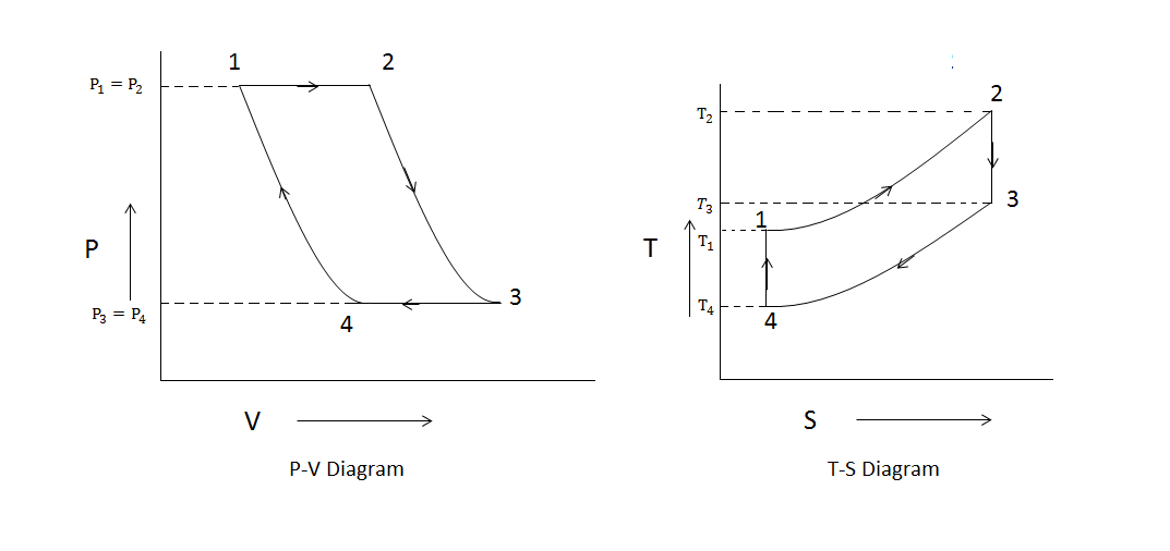
Brayton Cycle - pV - Ts Diagram

Steam Boiler: Working Principle of Gas Turbine
Closed Cycle Gas Turbine: Construction, Working, diagram - Mechanical

Gas turbine power plant- construction and working

mechanical engineering - Efficiency in a gas turbine or aircraft engine

Jet Engine Pv Diagram - Wiring Diagram

(a): Idealized Brayton cycle for gas turbines, (b): T-s Diagram, (c

Brayton Cycle - Gas Turbine Engine | Characteristics | nuclear-power.com